


I was called out to an aluminum extrusion plant where the shear cylinder on one of the presses wouldn’t hold position. I readjusted the valve’s pressure setting, and the problem was gone. I told the maintenance team the valve wasn’t broken; its setting had drifted off a long time ago. I think this is worth writing about, because far too many people blame hydraulic cylinder drift directly on a failed counterbalance valve, when in many cases the counterbalance valve setting is simply wrong or the lines are connected incorrectly.
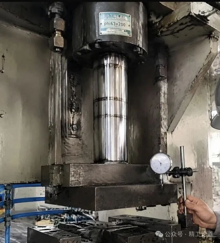
In a hydraulic system, the counterbalance valve is the “honest” type. Its construction isn’t complicated, but it’s stubborn. Mis-set it and it won’t sound an alarm right away; it will just let the cylinder slowly creep down. So the counterbalance valve is also called load-holding valve. Some people have measured drift rates anywhere from a few millimeters to several tens of millimeters per hour. That sounds small, but over time it adds up, and the machine starts making scrap. So don’t wait until the blade carrier comes crashing down to start thinking about it.
Counterbalance valve function and working principle
Before getting into the field cases, a quick refresher. The main function of a counterbalance valve is to hold a load in place when the directional valve is centered, and to stop the load from running away while it is being lowered. It also protects the load-holding side of the cylinder from pressure spikes.
The working principle is simple. The valve sits in the line on the load-holding side of the cylinder. Oil flowing into the cylinder passes freely through the built-in check valve. Oil flowing out is blocked until the valve opens, either because the load pressure reaches the setting, or because pilot pressure from the opposite cylinder line helps push it open. The higher the pilot ratio, the less pilot pressure it takes. That is why the counterbalance valve setting matters so much: set it too low, and the load alone can push the valve open.
In a hydraulic schematic, the counterbalance valve symbol looks like a pressure relief valve with a check valve drawn in parallel, plus a dashed pilot line running to the opposite side of the cylinder. When troubleshooting, get the machine’s hydraulic circuit diagram first and check that the valve, its pilot line and the return line are actually plumbed the way the diagram shows. Several of the faults below come down to a mismatch between the two.
Case: The counterbalance valve setting had drifted
Back to the extrusion press. Its counterbalance valve is a SUN CBEA, a cartridge valve installed in the manifold block on the cylinder’s cap-end (piston-side) line. The cylinder has a 63 mm bore and a 200 mm stroke. I had the operator raise the blade carrier to its highest position and then watched a dial indicator. After one minute, the rod had dropped about 0.8 mm. That isn’t fast, but it’s definitely not normal. A cylinder properly held by a counterbalance valve should drift less than 0.1 mm per minute, which is barely visible.
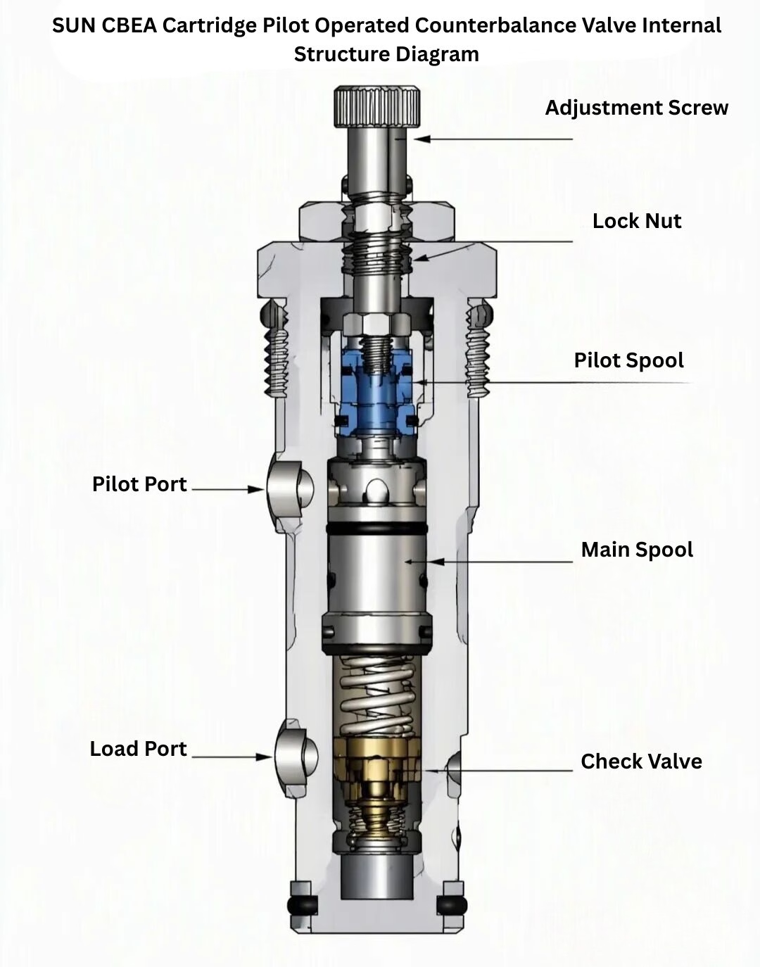
My diagnosis was that the counterbalance valve setting was too low. The CBEA is a pilot-assisted counterbalance valve with a built-in check valve for free reverse flow. The valve opens only when the cap-end pressure exceeds the setting, allowing the cylinder to lower. If the setting drifts, the valve sits half open, and the cylinder slowly bleeds off pressure and creeps down. The setting generally needs to be 30% to 40% above the load pressure. For example, if the load pressure is about 8 MPa, the counterbalance valve should be set to around 11–12 MPa. I connected a pressure gauge to the test port and found the actual setting was only 7 MPa. The load pressure had already pushed the valve open a crack, so of course it was drifting.
The right way to do a counterbalance valve adjustment
Counterbalance valve adjustment isn’t a matter of turning the screw at random. Many people start by turning it clockwise all the way in and then backing it out two turns. That approach does real harm. The adjusting screw has a lock nut. Loosen the lock nut first, then raise the setting based on the load pressure. I first set it to about 10 MPa, raised the blade carrier, and watched. The drift dropped from 0.8 mm per minute to 0.2 mm per minute. Still not enough. I went up to 12 MPa. This time the rod held, and the dial indicator barely moved. Tighten the lock nut. Done.
How the lines are connected to valve
Getting the setting right isn’t the only thing to check. The second point is how the lines are connected. I once ran into a different kind of drift on a lift table powered by a small hydraulic power unit. The counterbalance valve was mounted at the cylinder’s cap-end port, but the pilot line was connected wrong. According to the hydraulic schematic, the pilot pressure should have been taken from the rod side, but the fitter had connected the pilot line to the return line. As a result, the valve could never get enough pilot pressure and wouldn’t open. When lowering, the cylinder either didn’t respond or needed extremely high system pressure to force it down. The symptom of this fault is a cylinder that sinks instead of rising and won’t hold position. Once the line was reconnected to the correct port, the problem was solved. So “drift” with a counterbalance valve doesn’t always mean the cylinder is sliding down. Sometimes the valve isn’t closing and oil is escaping through the pilot line. Many people don’t know this.
Note that taking pilot pressure from the rod side assumes a double-acting cylinder. A counterbalance valve on a single acting cylinder has no pressurized rod-side line to pilot from, so the circuit needs a different layout. In that case, follow the valve maker’s recommended schematic instead of copying a double-acting circuit.
Return-line back pressure affacts
The third thing to check is back pressure on the return line. A counterbalance valve’s closing behavior is strongly affected by back pressure on the return side. If there’s a high-pressure filter on the return line, or the return throttle valve is set too far closed, back pressure rises. The valve relies on some back pressure to help it close, but if the back pressure is too high, the spool can’t return fully to its seat and won’t lock.
I once had a case where the cylinder lowered normally but crept down slowly as soon as it stopped. On inspection, the return throttle valve had been closed down to a sliver, and back pressure had reached 1.5 MPa. After opening up the throttle and bringing back pressure below 0.5 MPa, the drift stopped immediately. This trap is well hidden, and many people overlook it.
Selection: Choosing the right pilot ratio
Counterbalance valves come in different types. One more point to keep in mind. When selecting a counterbalance valve, the pilot ratio is a key parameter. SUN counterbalance valves, for example, are available with pilot ratios of 3:1, 4.5:1 and 7:1. The higher the pilot ratio, the higher the load pressure that a given pilot pressure can open against. But if the pilot ratio is too high, the valve becomes less stable and prone to chatter. So a higher pilot ratio isn’t always better. As a rule of thumb, use 4.5:1 for steady loads and 3:1 for loads with fluctuations and shocks. Get this choice wrong, and no amount of adjustment later will make it behave properly. I once saw a chatter problem on a lift platform caused by a counterbalance valve with a 7:1 pilot ratio: whenever the load fluctuated, the spool hunted back and forth. After it was replaced with a 4.5:1 valve, the chatter disappeared.
ملخص
When a cylinder drifts, don’t rush to pull the counterbalance valve and replace it. Check three things first: Is the valve setting high enough? Is the pilot line connected correctly? Is the return-line back pressure too high? Those three checks will reveal the cause of more than 90% of drift problems. Over the years I’ve adjusted dozens of counterbalance valves, and fewer than 20% of them actually had internal damage that required replacement. All the rest came down to counterbalance valve adjustment and plumbing. Yet on site, people see drift and immediately swap the valve. That’s not only wasted money: if the new valve goes in with the wrong setting, the problem stays.
A counterbalance valve is a lock. If the latch isn’t fully engaged, installing a new lock won’t help unless you set it up properly. It’s the same principle as adding oil to a gearbox: newer parts aren’t automatically better; what matters is whether everything is properly matched and adjusted. Every machine has its quirks, and you have to work with its logic.

