

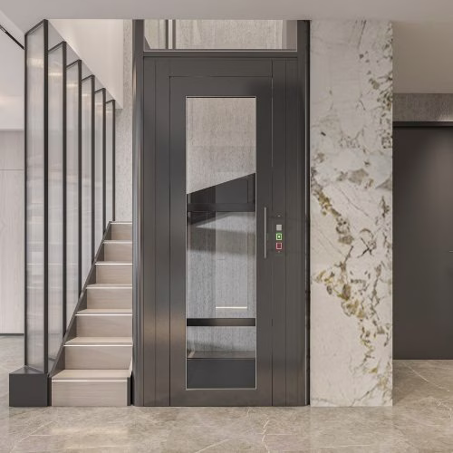
The hydraulic elevator power unit creates and controls pressurised fluid flow to lift-up and lower-down the elevator car/cabin/trolley using a hydraulic jack. The electrical energy supplied to the hydraulic pump is converted into hydraulic energy, enabling the lift to operate. Based on the type of hydraulic pump used in the hydraulic power unit, the application also changes and it is best practice to learn which hydraulic pump is best for a certain application.
Although there are various functions for each component used to build the hydraulic elevator power unit, some key functions are essential to understand.
Hydraulic Power Generation
An electric motor, coupled to a hydraulic pump (typically a gear, vane, or piston pump), is the primary power generation component in a hydraulic power unit. It created the necessary volumetric flow rate (GPM or L/min) and pressure (PSI or bar) to extend the ram at the required elevator speed against the load.
For instance, a 2500 lb (1134 kg) capacity elevator with a 5″ (127 mm) diameter ram typically operates at approximately 350-400 PSI static pressure. To achieve a design speed of 100 ft/min (0.5 m/s), the system would typically utilize a 30 HP (22 kW) motor driving a high-performance submerged screw pump to ensure quiet and vibration-free operation.
Key Components Inside a Hydraulic Elevator Power Unit
No matter the construction and functionality of the hydraulic elevator, the following components are always there in it:
| Component | Technical Role |
| Electric Motor | Drives the pump; may be dry-mounted or submersible. |
| Hydraulic Pump | Generates flow and pressure (gear, vane, or screw type). |
| Oil Reservoir (Tank) | Stores hydraulic fluid, enables cooling, and prevents cavitation. |
| Control/Directional Valves | Regulate ascent, descent, levelling, and pressure limits. |
| Muffler / Silencer | Reduces hydraulic pulsation and acoustic emissions. |
| Manifold Block | Houses integrated valve assemblies for compact design. |
| Pressure Gauge & Transducers | Provide real-time pressure feedback to the controller. |
Hydraulic Fluid Management and Pumping Function
The power unit contains an oil reservoir where hydraulic oil is stored and thermally conditioned. When the elevator is commanded to rise, the pump draws oil from this reservoir and delivers it into the system under pressure. Here comes the role of a directional control system to manage the movement of the elevator car. So, some technical considerations for fluid management are:
- Reservoir capacity must be able to help fluid cool down properly, prevent cavitation and keep the system stable.
- Filtration minimises contamination that can damage valves and pumps.
- Thermal control (oil coolers or heat exchangers) maintains constant viscosity for consistent performance.
The quality of fluid handling directly affects the smoothness of elevator rides, component life, and noise levels.
Directional Control & System Isolation
To direct pressurised fluid to the bottom of the jack to UP, allow fluid to return from the jack to the tank for DOWN, and block fluid paths in the STOP position to hold the car. This valve is a fail-safe, typically spring-biased to the “down” position in case of power loss. So, the main component is a solenoid-operated directional valve (normally a 4/3 or 3/3 configuration). For example, energising the “UP” solenoid shifts the valve spool, connecting the pump port (P) to the cylinder port (A), sending oil to the jack.
Precise Movement of Hydraulic Elevator Through Control Valve Assemblies
Beyond simply generating pressure, the hydraulic power units use control valves that regulate flow and ensure smooth operation (necessary for elevator function). These include:
- Up Valve, which controls the rate of oil entering the cylinder to manage acceleration.
- A down valve that modulates return oil flow to achieve controlled descent using gravity.
- Levelling valves allow micro-adjustments to guarantee ±3–5 mm levelling accuracy.
- A system relief valve protects the system from overpressure.
- Counterbalance (Holding) valve is a pilot-operated check valve located at or near the jack, and it holds the pressure in the system.
- And finally, safety valves that protect against over-pressure and uncontrolled motion.
All these valve assemblies provide closed-loop control, which helps in achieving a smooth and precise control to start, stop and level sequences as programmed.
Pressure Control & Load Holding
The relief valve is typically set at 140% of the maximum operating pressure (e.g., 700 PSI) to protect the system from structural overload. For safe descent, the system relies on a precision down control valve. Unlike common hydraulic systems, an elevator descends using gravity, controlled by the down solenoid valve. To ensure safety, the valve remains leak-tight when stationary, preventing any ‘drifting.’ During descent, the valve ensures a smooth, constant speed regardless of the load, while a rupture valve mounted directly on the jack provides ultimate protection against uncontrolled drops in the event of a hose failure.
Controlled Descent Using Gravity and Valve Modulation
The key difference between traction elevators and hydraulic elevators is, they use a pump to descend. Instead, when the controller commands a downward movement:
- The pump shuts off immediately.
- The down valve opens, allowing oil to return to the tank.
- Flow control valve (often integral to the directional valve or manifold) controls the oil flow.
- Gravity lowers the car, while the control valve regulates speed.
To meter (restrict) the flow of oil exiting the hydraulic jack during descent, thereby controlling the down speed independently of the car load. This ensures a constant, regulated descent regardless of passenger weight. For example, a needle valve or proportional orifice adjusts the flow path from the jack port (A) to the tank port (T) during the down cycle, maintaining speed at 100 ft/min whether the car is empty or at full load.
This energy-efficient design reduces electrical consumption because no power is required for descent, aside from control electronics.
System Conditioning & Stabilisation
Hydraulic elevators are inefficient, as most input energy converts to heat. This creates a necessity for the deployment of a heat exchanger. It then maintains oil viscosity and prevents system damage. Moreover, it requires that the tank must be sized to provide adequate fluid residence time for cooling and deaeration. For example, a 50 GPM system may have a 200-gallon tank and a 15-kW fan-cooled heat exchanger to keep oil temperature below 140°F (60°C).
Start-Up & Shutdown Control of Elevator
The hydraulic power unit prevents the elevator car from moving during a startup spike and manages thermal conditions. It uses a reset switch, a temperature switch, and a time-delay relay to bypass the Circuit. At startup, a solenoid briefly diverts pump flow directly to the tank until full pressure is achieved, preventing a car jump. Moreover, below a set point (e.g., 90°F), the control may turn off the heat exchanger fan. Above a high point, it may turn off the elevator until cooling occurs.
Classification of Hydraulic Power Units by Pump Type
Vane Pump Power Units
Blade (vane) pump power units are cost-effective and widely used. However, they exhibit higher operating noise and pressure pulsation, which can lead to vibration and resonance between the car and hydraulic cylinder. As a result, they are less suitable for installations requiring high comfort and low noise levels. Noise level ≈ 55 dB(A) (measured at 1 meter).
Arc Tooth Helical Gear Pump
The Arc Tooth Helical Gear Pump is an optimized design of gear pumps that has been introduced in recent years. It combines an arc-shaped tooth profile with a helical gear structure to optimize the meshing trajectory, reduce fluid pulsation, and is suitable for customers with specific performance requirements. Noise level ≈ 50 dB(A) (measured at 1 meter).
Three-Screw Pump Power Units
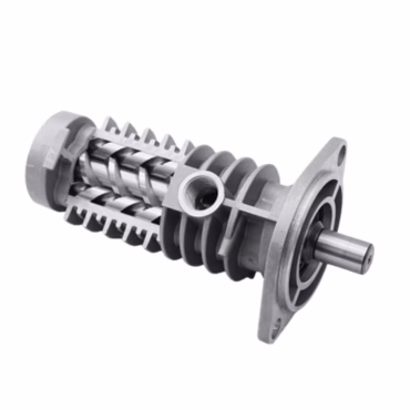
Three-screw pump power units are designed for high-end residential applications. Their defining advantages include:
- Smooth, continuous pressure output with almost no pulsation
- Significantly reduced vibration
- Extended service life due to minimal internal friction
These characteristics result in improved ride comfort, noise level ≈ 40 dB(A) (measured at 1 meter) and reduced maintenance requirements, and higher overall system reliability, making three-screw pumps the preferred solution for modern household hydraulic elevators.
Classification by Valve Control Mode
Two-Speed Valve Power Unit

The two-speed valve power unit controls descent by switching between fast and slow valves. This configuration allows basic acceleration and deceleration control and significantly improves ride comfort compared with traditional hydraulic elevators. It is suitable for most standard residential elevator applications.
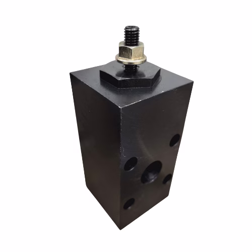
Three-Valve Power Unit (JL-36-4)

The three-valve system builds upon the two-speed design by adding a pressure protection valve. This enhancement prevents accidental self-descent caused by hydraulic leakage and ensures long-term floor-level holding. Noise performance and external dimensions remain similar to the two-speed unit, while safety and pressure retention are improved.
Proportional Valve Power Unit
Proportional valve power units represent the most advanced control solution. Using PLC coordination with a proportional valve amplifier, they enable real-time, precise adjustment of hydraulic flow during descent. This ensures:
- Seamless speed regulation
- Superior ride comfort
- Reduced dependency on installer expertise due to simplified debugging


These units are particularly suited for high-end hydraulic elevators where performance and comfort are critical.
Classification by Noise Performance
Low-Noise Power Units
Low-noise units, typically using blade pumps, operate at approximately 55–60 dB. They provide acceptable noise control for standard residential environments when paired with high-quality frequency converters.
Ultra-Silent Power Units
Ultra-silent power units employ three-screw pump technology combined with oil-immersed design and damping pads. Operating noise is reduced to approximately 43–45 dB with almost no perceptible vibration. These units are recommended for noise-sensitive environments such as villas and luxury homes.
Oil-Immersed Design and Safety Features
Oil-immersed power units integrate key components within the hydraulic oil, improving lubrication, heat dissipation, and noise suppression. Standard safety and maintenance features include:
- Manual emergency drop (manual oil discharge)
- Emergency maintenance shut-off valve
- Pressure gauge and overload protection
- Anti-extrusion detection interfaces
The improved emergency descent mechanism uses a self-reset knob structure, eliminating the need for tools and enabling rapid response during power failures
Hydraulic and Electrical Operating Principles
Ascending Operation
During ascent, a frequency converter precisely controls motor speed, providing smooth acceleration and deceleration. The inverter also enables conversion from single-phase household power to the three-phase supply required by the motor, solving a common residential installation challenge
Descending Operation
Descent control depends on the selected valve configuration:
- Two-speed and three-valve systems rely on timed valve switching and pressure compensation throttles
- Proportional valve systems use PLC signals to continuously regulate flow
These coordinated control strategies ensure stable operation under both light and heavy loads
Conclusion
The HPU’s design directly influences ride quality, noise levels, energy efficiency, and the overall reliability of the elevator system. For technicians, engineers, and building managers, understanding the HPU is essential for proper maintenance, troubleshooting, and system optimisation, making it one of the most important components in any hydraulic elevator installation.

