


HJL36 Elevator Submersible Low-Noise Power Unit
- Two Solenoid Valves have a dual-speed descending
- Frequency Converter Controls Motor Speed
- Built-in Pressure Compensation Throttle Valve
- Oil-immersed Motor and gear Pump or Three Screw pump
- Hand Pump Optional
- Description
- Hydraulic Schematic Diagram
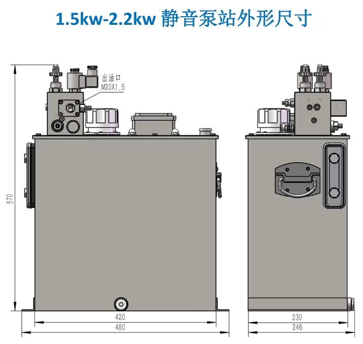
- Dimension of Elevator Power Unit
- Elevator Travel Speed Table
We have two different styles of the selected pump: Arc-tooth Helical Gear Pump power unit and three screw pump(3G) power unit.
Ascending control:
In the uplink process, the motor speed is accurately controlled by the frequency converter, and it works together
with the “hydraulic elevator pressure feedback stop valve” to ensure the stable uplink of the elevator. In the electronic
control system, the inverter plays an important role in the electronic control system:
1. Accurate control of acceleration and deceleration: In the process of the elevator, the frequency converter realizes
the smooth acceleration of the elevator by gradually increasing the power supply frequency (from 0Hz to 50Hz, about 3
seconds). When the elevator is close to the target floor, the inverter is triggered by the deceleration stroke switch to slow
down, and the power supply frequency is reduced to 20Hz (about 1 second) to ensure that the elevator slows down
smoothly to the flat level and stops accurately.
2. Voltage system conversion: In order to adapt to the home electricity environment, the inverter converthe
conventional single-phase 220V and 50Hz power supply into the three-phase 220V and 50Hz power supply required by the
elevator motor, so as to effectively solve the problem of no three-phase electricity in the home environment.
3. Provide certain protection measures for the elevator electric control system and motor.
Descending control:
In the descending process of the elevator, the two-speed valve plays a key role. The built-in pressure compensation
throttle valve in the power unit can automatically adjust the pressure of the hydraulic system according to the load
situation, to ensure that the elevator can operate smoothly under the conditions of heavy load and light load.
Two-speed valve (three-valve) switching mechanism:
In terms of control of solenoid valve, the sequence:
* When the elevator goes down, the control coil of the fast valve and the slow valve (the pressure protection valve of
three valves) is on at the same time to ensure that the elevator starts smoothly at an appropriate speed.
* When the elevator reaches the preset deceleration position, the fast valve stops working and the elevator begins to
gradually slow down.
* Whenthe elevator reaches the level position smoothly, the slow valve stops working and the elevator stops running.
* Finally, the pressure protection valve stops working after a delay of 2 seconds to ensure the stability and safety of
the hydraulic system.
Work Performance Comparison
| Control Method | Dual-Valve / Triple-Valve System | Imported Proportional Flow Valve System |
| Speed Smoothness | Stepped speed changes, noticeable jerk for passengers | Continuously variable speed control, smooth and continuous acceleration curve |
| Leveling Accuracy | ±10mm (relies on mechanical limit) | ±2mm (closed-loop correction with photoelectric switch) |
| Field Debugging | Requires higher debugging experience from workers | Easy debugging, only requires adjusting the control current of the amplifier board |


| Motor (Voltage)
| Motor (Power) | Pump Displacement | Rated Pressure | Cylinder speed ratio 1:2 | Cylinder speed ratio 1:3 | ||
| 63mm | 70mm | 63mm | 70mm | ||||
| 3-Phase 220V
| 1.5KW | 10ml/rev | 6MPa
| 9.3 | 7.6 | 13.9 | 11.4 |
| 2.2KW
| 12ml/rev | 11.2 | 9.1 | 16.8 | 13.6 | ||
| 14ml/rev | 13.0 | 10.6 | 19.5 | 15.9 | |||
| 3-Phase 380V
| 2.2KW | 14ml/rev | 13.0 | 10.6 | 6.5 | 5.3 | |
| 3.75KW | 19ml/rev | 17.7 | 14.5 | 8.85 | 7.25 | ||
| 5.5kw | 23ml/rev | 17.5 | 10.7 | 8.75 | |||
| 28ml/rev | 13 | 10.6 | |||||


