

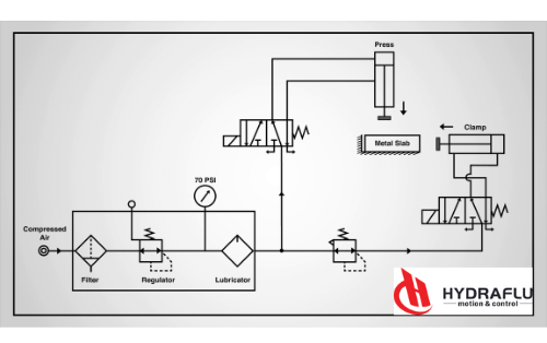
The main job of the spool valve is to control the direction of the flow of the energy source by either combining or switching the paths. Whether it is to be done through oil or air depends on in which system a spool valve is being operated in. Now I will mainly talk about the spool valve in the hydraulic system.
Let’s learn about how to read a Spool valve diagram and its representation in the system drawing. This will help you understand the operation of different configurations of the spool valve.
What is Spool Valve Working Principle?
The construction of a spool valve
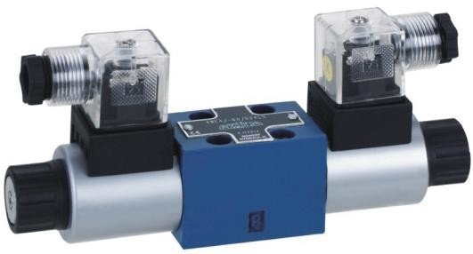
A spool type valve is a kind of directional control valve. Its core component is a cylindrical spool that moves within a matched sleeve or body to open and close flow paths between different ports, directiong fluid flow in hydraulic systems.
Let’s first learn about a Hydraulic Spool valve diagram and its representation in the system drawing. This will help you understand the operation of different configurations of the spool valve.
Explain the Operation of the Spool Valve
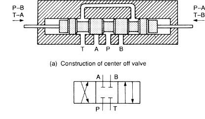
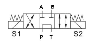
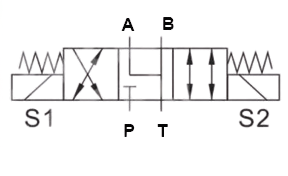
Let’s use a common directional valve to illustrate the working principle of the hydraulic spool valve. The diagram above shows the oil circuit schematic of a closed-center solenoid-operated valve, along with the corresponding spool valve schematic drawing.
In the de-energized state, the spool is usually held in a default position by a spring. In this state, flows are not allowed from all four ports. Port A and B are connected to the cylinders, and Port P is connected to the motor and pump, Port T is connected to the reservoir.
When the solenoid is energized, the generated electromagnetic force pushes or pulls the spool, compressing the spring and moving to a second position or third position. If the spool pushded to right, this new position alters the flow paths, from Port P to Port B, from Port A to Port T. If the spool pushed to the opposite direction, the flow paths will be from Port P to Port A, from Port B to Port T.
How to Read a Hydraulic Spool Valve Diagram
Now we can learn about how a spool valve is represented in engineering drawings and how to read a spool valve schematic drawing.
Spool Valve Symbol and Diagram
In engineering drawings, hydraulic schematic symbols provide detailed information regarding the valve they represent. Consequently, it is imperative to understand the symbols to ascertain the direction of the spool valve’s passage.
Symbols show:
- The methods of actuation
- The number of positions
- The flow paths
- The number of ports a valve has
When we see a spool valve schematic, we can see that it is made up of boxes indicating the number of possible positions the valve has. Each boxes contains several lines and arrows, which show flow paths. The symbols near both sides of the box indicate the actuation method, such as electromagnetic coils, springs, or pilot operation for switching the valve spool.
Schematic Diagrams for Common Spool Valve Configurations
Here are the diagrams for the key valve types mentioned in the article. The external lines connected to the boxes represent the ports (P, T, A, B, etc.). The internal lines and arrows show the flow paths for each position.
1. 2/2 Valve (2-Way, 2-Position)
This is a simple on/off valve. The actuation method is by electromagnetic coil. Its function is to control flow between an inlet (P) and an outlet (A).
- Position 1 (left ): The line connecting the P and A ports shows that flow can pass through the valve.
- Position 2 (right): The blocked line shows that the path is closed. No flow can pass.
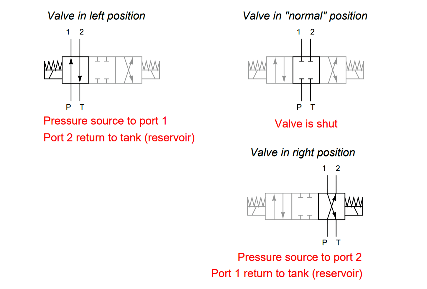
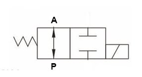
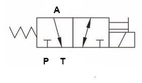
2. 3/2 Valve (3-Way, 2-Position)
This valve is common for controlling single-acting cylinders. The default position is often spring-return. Its function is that in one position, it sends pressure to an actuator (A). In the other, it exhausts the actuator (A to T).
Reading the Diagram:
- Actuated Position (left ): Pressure (P) flows to the work port (A). The tank port (T) is blocked.
- Return Position (Right ): The work port (A) is connected to the tank/exhaust (T). Pressure (P) is blocked. This allows the spring in a single-acting cylinder to retract, pushing the fluid out through T.
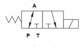
Reading the Diagram:
- Default Position (left ): The work port (A) flows to the tank port (T). Pressure (P) is blocked. This allows the spring in a single-acting cylinder to retract, pushing the fluid out through T.
- Return Position (Right ): The work port (A) is blocked. Pressure (P) is connected to the tank/exhaust (T).
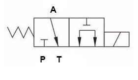
Reading the Diagram:
- Default Position (left ): The work port (A) flows to the tank port (T). Pressure (P) is blocked. This allows the spring in a single-acting cylinder to retract, pushing the fluid out through T.
- Return Position (Right ): Pressure (P) flows to the work port (A). The tank port (T) is blocked.
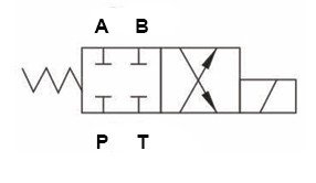
3. 4/2 Valve (4-Way, 2-Position)
This kind of valve is common for controlling double-acting cylinders. Its function is that in one position, it sends pressure to an actuator (A) and, simultaneously, exhausts the actuator (B to T). In another position, it sends pressure to an actuator (B) and, simultaneously, exhausts the actuator (A to T).

Reading the Diagram:
- Default Position (left ): Pressure (P) flows to the work Port (A) , Port (B) connects to tank Port (T)
- Return Position (Right ): Pressure (P) flows to the work port (B). Port (A) connects to tank Port (T)
Reading the Diagram:
- Default Position (left ): Valve is blocked. No flow paths through the valve.
- Return Position (Right ): Pressure (P) flows to the work port (B). Port (A) connects to tank Port (T)
4. 4/3 Valve (4-Way, 3-Position) – Four Common Centre Configurations
This is the most critical valve for hydraulic systems. The centre position behaviour is what differentiates them.
1.Closed Centre Valve
All ports are blocked in the centre position.
By stopping pump flow, this locks the actuator, preventing movement, a feature that requires a pump relief valve.
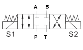
2.Open Center Vavle
Port P, Port A and B, are all connected to Port T
The function of this valve, as illustrated in the diagram, is to unload the pump by directing the actuator to its neutral position.
3.Tandem Center Valve
Port P is connected to T in the centre, while A and B are blocked.
This valve unloads the pump by returning its flow to the tank at low pressure, thereby locking the actuator in place.
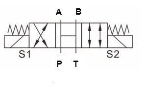
4.Float Center Valve
Port P is blocked while Port A, B, and T are connected
This graphic spool valve symbol shows that its function is to keep the pump pressure constant with the actuator being neutral.
How to Use Hydraulic Spool Valve Diagrams
Follow the Routes
Follow the lines and arrows within the corresponding box for any given valve position. Identify the terminals that are active and those that are inactive.
Relate to the Actuator
The actuator’s action (extend, retract, lock, or float) can be determined by determining the state of terminals A and B.
Evaluate the System
The efficacy, energy efficiency, and safety of the system are directly influenced by the configuration of the centre position.

