

Most industries today depend on heavy machinery and rugged equipment to lift heavy loads, move large volumes of materials, and more. All these tools depend on pressurized lines for hydraulics, fuel delivery, and more. Specialized threads are often utilized to form reliable sealed connections for hydraulic fluid or liquid fuels to flow at high pressure levels effectively for hundreds or thousands of hours without failure.
These special threads are available in many different specifications, such as NPT, BSPT, JIS, and more, and understanding the differences between the specifications is essential to ensure proper seals and reliable equipment operation. Different thread specifications cannot be matched to one another, or a seal failure will occur, which is why professionals must be able to spot the differences before making dangerous mistakes when making repairs or upgrades to pressurized lines or other threaded fittings.
Identifying the Major Thread Types
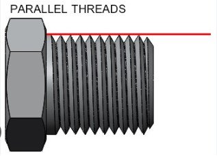
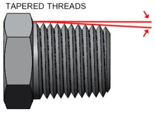
There are many different parallel and tapered thread patterns to be aware of. Once you understand that parallel threads maintain a straight profile while tapered threads go from wider to narrower, you can move on to identifying the different profiles that allow you to identify various specifications such as NPT, BSP, JIS, SAE, or Metric.
 |  |
NPT/NPTF Thread Type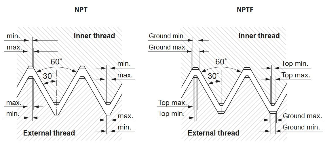
- NPT – National Pipe Thread
- NPTF – National Pipe Thread Fuel
- Tapered thread design
- Provides a reliable seal
- Commonly used in North and South America
- 60-degree thread angle
- NPT markings
NPT or NPTF stands for National Pipe Thread, and these threads utilize a tapered design. Both NPT and NPTF threads are tapered, but NPT requires the addition of a sealant, such as teflon tape, for a reliable seal. NPTF threads are made to crush to a tighter mechanical seal and provide an effective dry seal that’s preferable for higher pressure uses and for hydraulic systems where NPT sealants could potentially contaminate the lines over time. NPT fittings and commonly feature an “NPT” marking for identification, but not all NPT fittings have this indicator.
NPT/NPTF Thread Size Chart
| Dash Size(Nominal Size) | Thread Pitch | Male Thread O.D. mm | Male Thread O.D. inches | Female Thread I.D. mm | Female Thread I.D. inches |
| -02 (1/8) | 27 | 10.3 | 0.41 | 9.4 | 0.37 |
| -04 (1/4) | 18 | 13.7 | 0.54 | 12.4 | 0.49 |
| -06 (3/8) | 18 | 17.3 | 0.68 | 15.7 | 0.62 |
| -08 (1/2) | 14 | 21.3 | 0.84 | 19.3 | 0.76 |
| -10 (5/8) | 14 | 22.9 | 0.90 | 21.1 | 0.83 |
| -12 (3/4) | 14 | 26.9 | 1.06 | 24.9 | 0.98 |
| -16 (1) | 11½ | 33.3 | 1.31 | 31.5 | 1.24 |
| -20 (1 ¼) | 11½ | 42.2 | 1.66 | 40.1 | 1.58 |
| -24 (1 ½) | 11½ | 48.3 | 1.90 | 46.2 | 1.82 |
| -32 (2) | 11½ | 60.4 | 2.38 | 57.9 | 2.29 |
*O.D. = Outside Diameter I.D. = Inside Diameter
BSP Thread Type
- British Standard Pipe
- BSPP – Parallel threads
- BSPT – Tapered threads
- Used heavily in Europe, the UK, India, Australia, and NZ
- G, R, or Rp markings
- 55-degree thread angle
The BSP in the thread standard stands for British Standard Pipe and is a standard used heavily throughout Europe, the UK, and Australia. This standard has a 55-degree thread angle and is offered with both tapered and parallel thread patterns. Although this standard is very similar to NPT, it is not compatible, and when BSP and NPT fittings are combined, leaks will occur. BSP fittings are commonly marked with “G”, “R”, or “Rp” for identification purposes.
BSP Thread Size Chart
| Dash Size(Nominal Size) | Thread Pitch | Male Thread O.D. mm | Male Thread O.D. inches | Female Thread I.D. mm | Female Thread I.D. inches |
| -02 (1/8) | 28 | 9.7 | 0.38 | 8.9 | 0.35 |
| -04 (1/4) | 19 | 13.2 | 0.52 | 11.9 | 0.47 |
| -06 (3/8) | 19 | 16.5 | 0.65 | 15.2 | 0.60 |
| -08 (1/2) | 14 | 20.8 | 0.82 | 19.1 | 0.75 |
| -10 (5/8) | 14 | 22.4 | 0.88 | 20.3 | 0.80 |
| -12 (3/4) | 14 | 26.4 | 1.04 | 24.6 | 0.97 |
| -16 (1) | 11 | 33.0 | 1.30 | 31.0 | 1.22 |
| -20 (1 ¼) | 11 | 41.9 | 1.65 | 39.6 | 1.56 |
| -24 (1 ½) | 11 | 47.8 | 1.88 | 45.5 | 1.79 |
| -32 (2) | 11 | 59.7 | 2.35 | 57.4 | 2.26 |
*O.D. = Outside Diameter I.D. = Inside Diameter
JIS Tapered Pipe Thread Type
- Japanese Industrial Standards
- 55-degree thread angle
- 30-degree end flare
- JIS Marking
- Heavily used in Japan, Korea, and China
JIS is a well-known thread standard that’s heavily used throughout Asia. JIS stands for Japanese Industrial Standards, and this standardized thread design is very similar to the BSP thread style. JIS fittings are available in both parallel and tapered designs and can often be used alongside BSP fittings, but an additional sealant must be included for an effective seal.
Sometimes, JIS fittings feature a “JIS” marking, making it simple to identify the standard. Without the markings, users should look for the 30-degree flare at the end of a JIS connection or a 37-degree flare for a JIC connection.
JIS Thread Size Chart
| Dash Size(Nominal Size) | Thread Pitch | Male Thread O.D. mm | Male Thread O.D. inches | Female Thread I.D. mm | Female Thread I.D. inches |
| -02 (1/8) | 28 | 9.4 | 0.37 | 8.1 | 0.32 |
| -04 (1/4) | 19 | 13.7 | 0.53 | 12.4 | 0.49 |
| -06 (3/8) | 19 | 17.2 | 0.68 | 16 | 0.62 |
| -08 (1/2) | 14 | 21.5 | 0.84 | 19.8 | 0.77 |
| -10 (5/8) | 14 | 23.1 | 0.91 | 20.6 | 0.81 |
| -12 (3/4) | 14 | 26.9 | 1.06 | 25.4 | 1 |
| -16 (1) | 11 | 34 | 1.34 | 31.8 | 1.25 |
| -20 (1 ¼) | 11 | 42.6 | 1.68 | 40.4 | 1.59 |
| -24 (1 ½) | 11 | 48.5 | 1.9 | 46.2 | 1.81 |
| -32 (2) | 11 | 60.4 | 2.37 | 58.2 | 2.29 |
*O.D. = Outside Diameter I.D. = Inside Diameter
SAE Thread Type
SAE threads are regulated by the Society of Automotive Engineers. These threads are most often straight and rely on o-rings for an effective liquid seal. SAE threads and fittings are often used for mechanical fittings and are relied upon less for liquid or gas sealed fittings than NPT. Anyone identifying an SAE thread should utilize an SAE pitch gauge to determine its size. SAE fittings commonly have SAE markings and an inch marking.
SAE Thread Size Chart
| Dash Size(Nominal Size) | Thread Pitch | Male Thread O.D. mm | Male Thread O.D. inches | Female Thread I.D. mm | Female Thread I.D. inches |
| -02 (1/8) | 24 | 3.9 | 0.31 | 6.9 | 0.27 |
| -03 (3/16) | 24 | 9.6 | 0.38 | 8.6 | 0.34 |
| -04(1/4) | 20 | 11.2 | 0.44 | 9.9 | 0.39 |
| -05(5/16) | 20 | 12.7 | 0.5 | 11.4 | 0.45 |
| -06(3/8) | 18 | 14.2 | 0.56 | 12.9 | 0.51 |
| -08(1/2) | 16 | 19 | 0.75 | 17 | 0.67 |
| -10(5/8) | 14 | 22.3 | 0.88 | 20.3 | 0.8 |
| -12(3/4) | 12 | 26.9 | 1.06 | 24.9 | 0.98 |
| -14(7/8) | 12 | 30 | 1.18 | 27.7 | 1.09 |
| -16(1) | 12 | 33.3 | 1.31 | 31 | 1.22 |
| -20(1 ¼) | 12 | 41.4 | 1.63 | 39.1 | 1.54 |
| -24(1 ½) | 12 | 47.7 | 1.88 | 45.5 | 1.79 |
| -32(2) | 12 | 63.5 | 2.5 | 61.2 | 2.41 |
*O.D. = Outside Diameter I.D. = Inside Diameter
Metric thread type
Metric threads are standardized by the ISO, or International Organization for Standardization. A bolt or another fitting with metric threads is commonly identified by the presence of the letter “M” along with a diameter value. Metric threads are most often used in fasteners or mechanical fittings and typically rely on parallel threads, though some tapered varieties exist as well.
Metric threads are used heavily throughout Europe and many other areas around the world. A metric thread pitch gauge should be used to identify a specific thread pattern appropriately.
Metric Thread Size Chart
| SI Metric Port Size mm | Thread Pitch mm | Male Thread O.D. mm | Male Thread O.D. inches |
| M5 × 0,8 | .8 | 5 | 0.1968 |
| M8 × 1,0 | 1 | 8 | 0.3150 |
| M10 × 1,0 | 1 | 10 | 0.3937 |
| M12 × 1,5 | 1.5 | 12 | 0.4724 |
| M14 × 1,5 | 1.5 | 14 | 0.5512 |
| M16 × 1,5 | 1.5 | 16 | 0.6299 |
| M18 × 1,5 | 1.5 | 18 | 0.7087 |
| M22 × 1,5 | 1.5 | 22 | 0.8661 |
| M27 × 2,0 | 2 | 27 | 1.063 |
| M33 × 2,0 | 2 | 33 | 1.299 |
| M42 × 2,0 | 2 | 42 | 1.654 |
| M50 × 2,0 | 2 | 50 | 1.969 |
| M60 × 2,0 | 2 | 60 | 2.362 |
*O.D. = Outside Diameter
Alternatives To Threaded Fittings for Hydraulic Applications
Hydraulic systems rely heavily on threaded fittings because they’re simple to use, versatile, and reliable. Threaded fittings are not the only option available, however. There are fittings that rely on compression, flange, push-to-connect, ORFS (o-ring face seal), or quick couplings.
Compression Fittings
A compression fitting relies on a compressible metal material that’s squeezed into a narrow profile that locks the pipe into position. Compression fittings are preferred in situations where the pipe to be attached cannot be spun, and soldering is difficult or impossible. The pipe is placed inside the compression fitting and a tool is used to squeeze the compression portion of the fitting to crimp the pipe into position forming a reliable seal.
Push-To-Connect
Push-to-connect fittings are sometimes used in hydraulic installations where simplicity and speed are the two most important factors. These robust fittings rely on a tapered female fitting, often equipped with barbs and an O-ring seal. As the pipe is pressed into the fitting the specially shaped female fitting snugs the pipe into position so it cannot be removed without disengaging the lock. Push-to-connect fittings are more costly, and many experts believe them to be less reliable than threaded fittings, but they are fast and convenient.
ORFS
An ORFS or o-ring face seal fitting relies on an o-ring built into the lip of a connection and a thread fitting for a durable seal. These fittings are often a bit more costly than threaded fittings but deliver superior long-term protection in many settings.
Quick Couplings
Quick couplings are easy to connect and disconnect while providing a seal by pressing flared male and female sections together with a rubber or another compressible material on each side. The coupling action presses the rubber to form a reliable seal that can quickly be reversed by uncoupling the fitting. They are ideal for situations where frequent connection and disconnection are required but are less reliable for long-term seals versus threaded fittings.
Conclusion
With so many different thread standards used around the world, it’s important to understand their differences and to know how to identify the standard used on your equipment. Use this guide to identify the proper fittings for any repairs or upgrades you make, and you’ll enjoy reliable performance.

